General Dynamics Engineers Built a CAN Bus System From Scratch
General Dynamics sent a mixed-experience engineering team to a CANbus Academy workshop. By mid-morning on Day 3, they had a working SAE J1939 system — 8 independently programmed ECU nodes on an 11-meter CAN Bus — designed, wired, coded, and integrated by the engineers themselves.
The Problem: Slides Don’t Build Networks
General Dynamics had active vehicle platform programs that required CAN Bus expertise. The 10-person engineering team came from diverse backgrounds — some had embedded systems experience, others were mechanical or systems engineers who had never scoped a CAN frame on an oscilloscope. Everyone needed to reach the same level of proficiency, under real program deadlines.
The team had evaluated lecture-based CAN training options. The problem with that approach: engineers who sit through slides can repeat definitions on a quiz, but they can’t design a CAN network topology, program an ECU from scratch, or diagnose an intermittent bus fault under time pressure. Those are the skills the vehicle programs actually needed.
General Dynamics chose CANbus Academy’s workshop format specifically because it’s hands-on — every concept is proved on real hardware before moving to the next one. No simulations. No pre-wired demo boards. Engineers build everything themselves.
The Workshop: 3 Days, Protocol to Full System
CANbus Academy delivered a 3-day on-site workshop structured as a progressive build. Each day’s exercises produced working hardware that fed into the next day’s project. Nothing was thrown away — the ECU nodes built on Day 2 became the system integrated on Day 3.
Day 1 — CAN Protocol Foundations
The first day covered CAN 2.0B fundamentals — frame structure, arbitration, error handling mechanisms, and physical layer design. But the classroom portion was just the setup for the lab.
Engineers connected oscilloscopes and protocol decoders to live CAN buses. They measured bit timing, observed arbitration in real-time, and decoded raw frames by hand — before touching any software tools. The point: understand what the tools are showing you before you trust them.
By afternoon, each engineer had built a 3-node CAN system and written a basic CAN Analyzer application using Arduino prototyping platforms — reading and transmitting messages on the bus they’d wired themselves.
Skills practiced: CAN frame decoding, oscilloscope-based physical layer analysis, bit timing measurement, basic CAN transmit/receive programming.
Day 2 — ECU Design & SAE J1939
Day 2 shifted from protocol to product. The morning covered embedded systems architecture: real-time operating concepts (comparing anti-lock braking response times to general-purpose computing), core selection, bootloader design, and software stack development.
The lab exercises progressed from fundamentals to real actuator control: digital outputs, PWM (pulse-width modulation) outputs, analog inputs, signal processing, and bi-directional motor speed control using H-bridge circuits. Each exercise built on the previous one — by end of day, every engineer had a functioning ECU node that could read sensors, drive motors, and communicate over SAE J1939 with defined PGNs and SPNs.
Skills practiced: ECU hardware design, embedded C programming, SAE J1939 message definition (PGNs, SPNs), PWM motor control, H-bridge circuit design, sensor input processing.
Day 3 — Full System Integration
The final day was the proof. The 10 engineers split into 5 teams, each responsible for a subsystem of a multi-ECU vehicle architecture. The assignment: design and integrate an 8-ECU system with distributed control across propulsion, turret, supervision, information display, and user input.
The 8-ECU architecture:
- 2 propulsion ECUs — joystick-controlled drive motors
- 2 turret motor ECUs — servomotor control (altitude and azimuth)
- 1 supervisor ECU — system coordination and safety
- 1 information system ECU — real-time display of speed, direction, and turret position
- 2 user input controllers — operator interface via joysticks
All 8 nodes connected on a single 11-meter CAN Bus spanning five workstation tables. The system was operational by mid-morning — joystick inputs driving propulsion motors, servos tracking turret commands, and a live overhead display showing system state across all nodes.
The rest of Day 3 covered what happens after the prototype works: ECU manufacturing processes (breadboard to PCB), physical layer considerations for production CAN networks, functional safety protocols (PHA and SIL assessments), and regression testing via hardware-in-the-loop simulation.
Skills practiced: Multi-ECU system architecture, CAN Bus integration and commissioning, bus load validation, arbitration conflict diagnosis, end-to-end message flow verification, manufacturing transition planning, functional safety assessment.
Workshop Equipment & Materials
Every engineer worked at their own station with dedicated hardware throughout the 3 days. Nothing was shared or pre-configured — each participant built their setup from components.
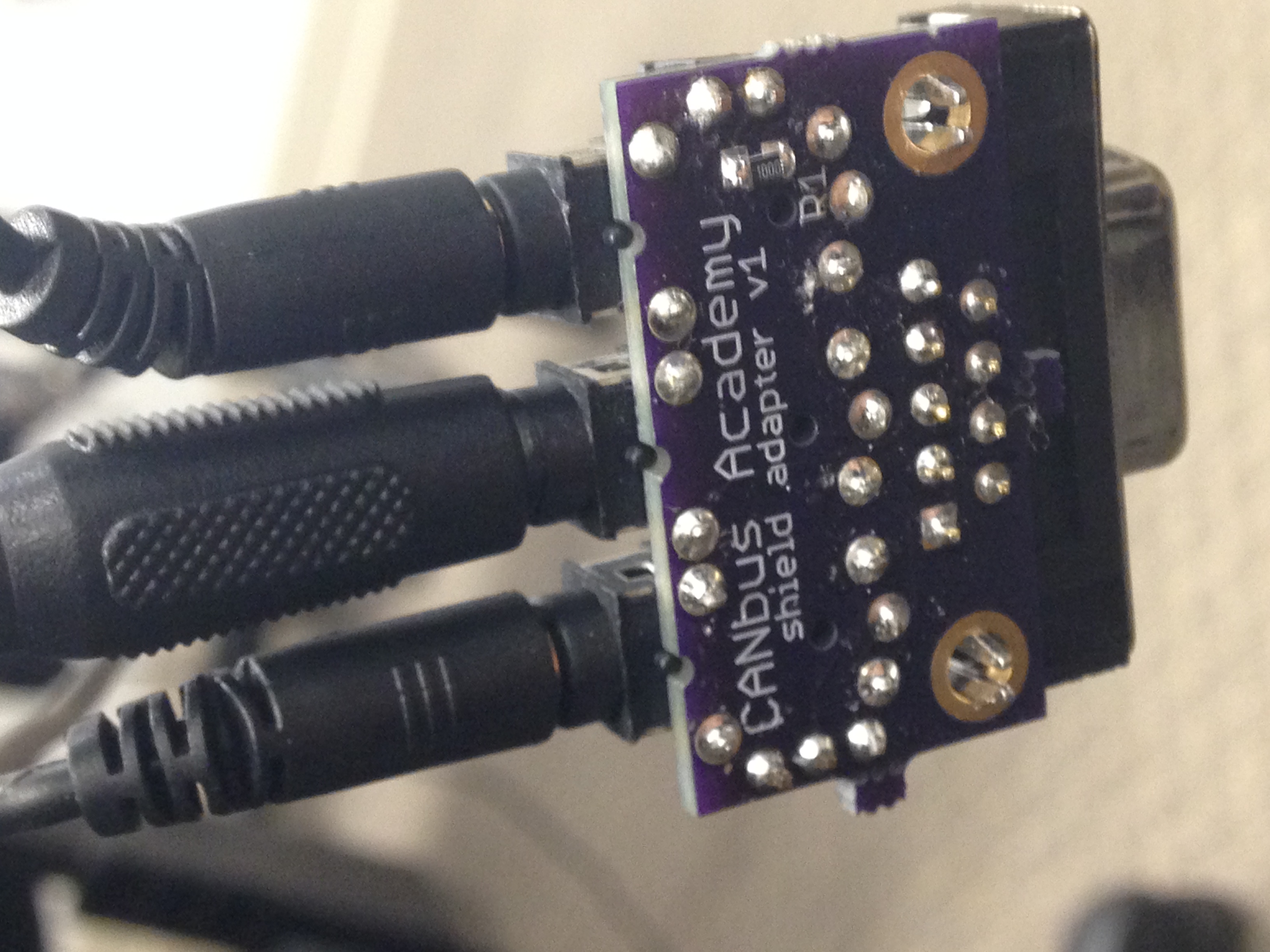 CAN adapters and prototyping hardware
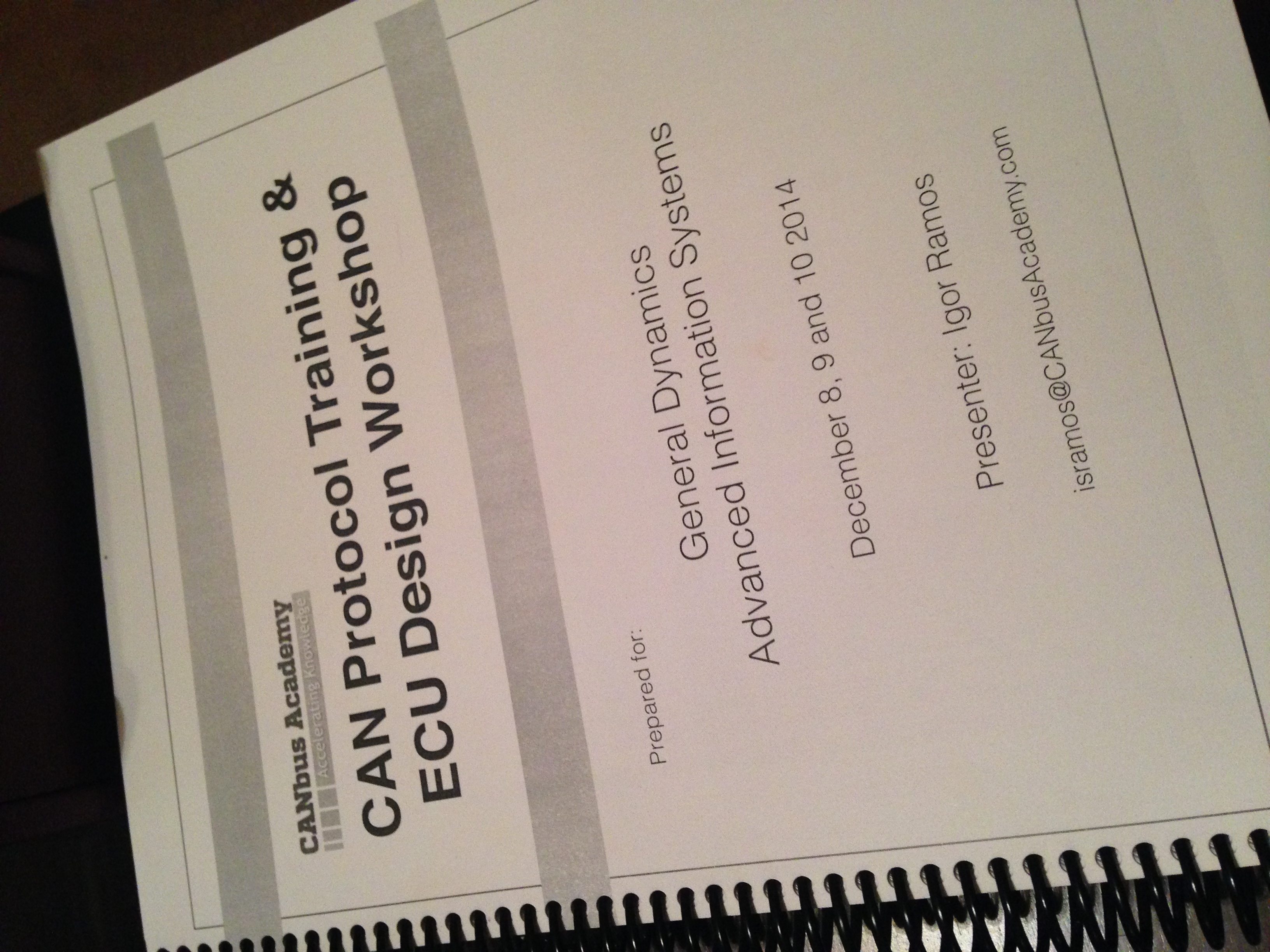 Workshop handbook and reference materials
 Individual component kits per engineer
Each station included: Arduino-based prototyping platform, CAN transceiver modules, oscilloscope access, protocol decoder, breadboard and wiring components, DC motors, servomotors, joystick controllers, and H-bridge motor driver circuits. All materials were provided by CANbus Academy — teams brought nothing but laptops.
The Result
No simulation. No demo board someone else pre-wired. No slideshow with a quiz at the end. The General Dynamics team built a working multi-ECU CAN Bus system from scratch — 8 nodes, 11 meters of physical bus, SAE J1939 message traffic, designed, programmed, and integrated by the engineers themselves in under 3 days.
Skills the team took back to their vehicle programs:
- CAN 2.0B protocol analysis — frame-level understanding, not just tool output
- SAE J1939 message architecture — PGN/SPN definition, scheduling, and validation
- ECU design from components — hardware selection, embedded software, actuator control
- Oscilloscope-based diagnostics — physical layer debugging, bit timing verification
- Multi-node integration — bus topology, load analysis, arbitration conflict resolution
- Manufacturing readiness — breadboard-to-PCB transition, functional safety basics
Every engineer left with the workshop handbook, their own ECU code, and the ability to apply these skills immediately to active programs — not a certificate and a set of lecture notes.
Why a Workshop Instead of a Course
Most CAN Bus training follows the lecture format: slides, maybe a pre-wired demo, a certification test. Engineers retain the terminology for a few weeks but can’t apply it when they’re back at their desks facing a real bus fault or a new ECU design.
The workshop format is different. Engineers build real hardware from Day 1. They make mistakes with a scope probe in their hand, not in a multiple-choice exam. They debug their own wiring, their own code, their own bus topology — the same problems they’ll face on their actual vehicle programs.
The difference shows in the output. A lecture-trained engineer can define a CAN frame. A workshop-trained engineer can design one, transmit it, capture it on a scope, decode it, and troubleshoot it when it doesn’t arrive. The General Dynamics team reached that level in 3 days because every hour was spent building, not watching.
CANbus Academy workshops are structured as progressive builds — each day’s output becomes the next day’s input. Nothing is thrown away, nothing is pre-built. By the end, the system the team integrates is made entirely of components they designed and programmed themselves. That’s the difference between training and a workshop.
— Engineering Lead, General Dynamics“[Placeholder — real testimonial from GD engineering team to be added when available.]”
Common Questions About On-Site Workshops
How long is a CAN Bus workshop?
The standard workshop is 3 days. Day 1 covers CAN protocol and physical layer. Day 2 covers ECU design and SAE J1939. Day 3 is full system integration. Shorter formats (1-2 days) are available for teams that only need protocol-level training without ECU design.
What experience level do engineers need?
The workshop is designed for mixed-experience teams. The General Dynamics group ranged from embedded systems engineers to mechanical engineers with no prior CAN exposure. The progressive structure — fundamentals first, then design, then integration — means everyone builds from the same foundation.
What does each engineer take away?
Every participant keeps the workshop handbook and all code they wrote during the exercises. More importantly, they leave with hands-on experience designing ECU hardware, writing embedded CAN software, using oscilloscopes for physical layer diagnosis, and integrating multi-node systems — skills that transfer directly to their vehicle programs.
Do you provide all equipment?
Yes. CANbus Academy provides all prototyping hardware, CAN transceivers, oscilloscopes, protocol decoders, motors, sensors, and components. Each engineer gets their own dedicated workstation. Teams only need to bring laptops.
Can the workshop be customized for our vehicle platform?
Yes. The protocol coverage (CAN 2.0B, SAE J1939, CANopen, CAN FD) and the final integration project can be tailored to your team’s specific application domain. Contact Igor to discuss your team’s requirements.
Where are workshops held?
Workshops are delivered on-site at your facility. CANbus Academy ships all equipment and materials. This minimizes travel for your team and allows exercises to reference your specific vehicle platform context.
Train Your Engineering Team
Your engineers build real CAN Bus hardware — not slideshows. CANbus Academy workshops are tailored to your team’s experience level and vehicle platform, from protocol fundamentals through full system integration.
Available on-site at your facility or remote.